Pumps Guide
for the Red Seal Millwright Exam
Centrifugal and positive displacement pumps, mechanical seals, cavitation, and troubleshooting explained for the Red Seal Millwright exam — installation, maintenance, and failure analysis.
Pumps in the Millwright Trade
Millwrights install, align, maintain, and troubleshoot pumps across virtually every industrial sector — water treatment, oil and gas, manufacturing, power generation, and process industries all depend on pumping systems. Pump knowledge appears across multiple NOA blocks: installation and alignment, mechanical seals, troubleshooting, and preventive maintenance all have pump components.
The Red Seal exam tests pumps at the level of a millwright who works on them — selecting the right pump type for the application, understanding how each type works, diagnosing failure from symptoms, and maintaining mechanical seals correctly.
Pump Classification
All pumps fall into two fundamental categories based on how they move fluid:
Dynamic Pumps
Impart velocity to the fluid, which converts to pressure. Flow is continuous and relatively smooth. Output pressure varies with flow rate.
Positive Displacement Pumps
Trap a fixed volume of fluid and force it through the discharge. Flow is proportional to speed and largely independent of pressure. Output pressure is determined by system resistance.
Centrifugal Pumps
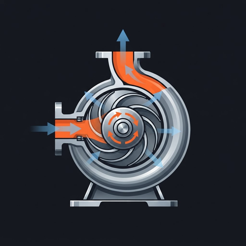
The most common pump type in industrial applications. A centrifugal pump is a dynamic pump — it uses a rotating impeller to impart kinetic energy to the fluid, which converts to pressure in the volute casing.
How It Works
The impeller rotates inside the volute casing. Fluid enters at the centre of the impeller (the eye) and is flung outward by centrifugal force. As fluid moves from the impeller into the wider volute casing, velocity decreases and pressure increases (Bernoulli's principle). The fluid exits through the discharge nozzle.
Impeller Types
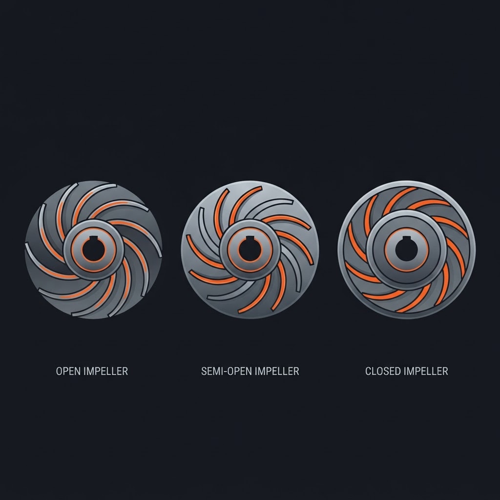
Open Impeller
Vanes with no shrouds. Simple, easy to clean, tolerates solids and fibrous materials. Lower efficiency. Used in wastewater and slurry applications.
Semi-Open Impeller
Vanes with one shroud (back plate only). Balance between efficiency and tolerance for solids.
Closed Impeller
Vanes enclosed between two shrouds. Highest efficiency. Best for clean fluid applications. Most common in industrial service.
Centrifugal Pump Characteristics
Performance Curve
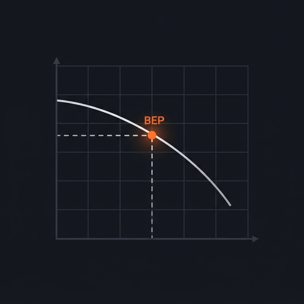
A graph showing the relationship between flow rate (Q) and head (H) at a given speed. As flow increases, head decreases. The operating point is where the pump curve intersects the system curve.
Shutoff Head
The maximum head a centrifugal pump produces at zero flow. The pump should never run at shutoff head for extended periods — the energy goes into heating the fluid with no flow to carry the heat away.
Best Efficiency Point (BEP)
The flow rate at which the pump operates most efficiently. Running significantly away from BEP causes radial loads on the shaft, increased wear, and reduced seal and bearing life.
Affinity Laws
Govern how pump performance changes with speed:
EXAM TIP
The affinity laws are directly testable. Doubling pump speed doubles flow, quadruples head, and increases power by eight times. Cutting speed in half with a VFD reduces power consumption to one-eighth — which is why VFDs are used for energy savings on centrifugal pumps.
Affinity Laws Calculator
Adjust pump speed to see how flow, head, and power change
Initial Conditions (Speed 1)
New Speed (Speed 2)
Try it: Double the speed (set N₂ = N₁ × 2) and watch power increase by 8× — that's why VFDs save so much energy on centrifugal pumps.
Centrifugal Pump Installation
Alignment
Pump and driver must be aligned within specification before coupling connection. Thermal growth during operation must be accounted for — the pump may need to be intentionally misaligned cold to be in alignment at operating temperature.
Suction Piping — Critical to Performance
- 1Suction pipe diameter should be equal to or larger than the pump suction nozzle
- 2Minimize elbows and fittings on the suction side — each fitting increases resistance and reduces available NPSH
- 3Suction line should slope upward toward the pump to prevent air pockets
- 4Never reduce the suction pipe diameter — a reducer on the suction side must be eccentric, flat side up, to prevent air accumulation
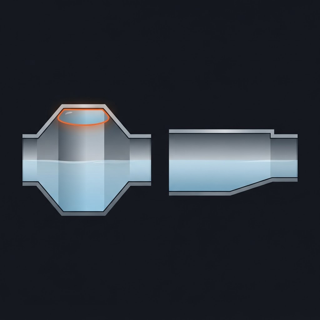
Eccentric Reducer — Flat Side Up on Suction
This is a specific, testable installation requirement. A concentric reducer on the suction side creates an air trap at the top of the pipe — this air pocket causes cavitation and erratic pump performance.
Grouting
Pump baseplate grouted to foundation to provide rigid, vibration-resistant support. Alignment must be completed and baseplate checked for levelness before grouting.
Cavitation
Cavitation is one of the most important and most tested pump topics on the Red Seal exam.
What Is Cavitation
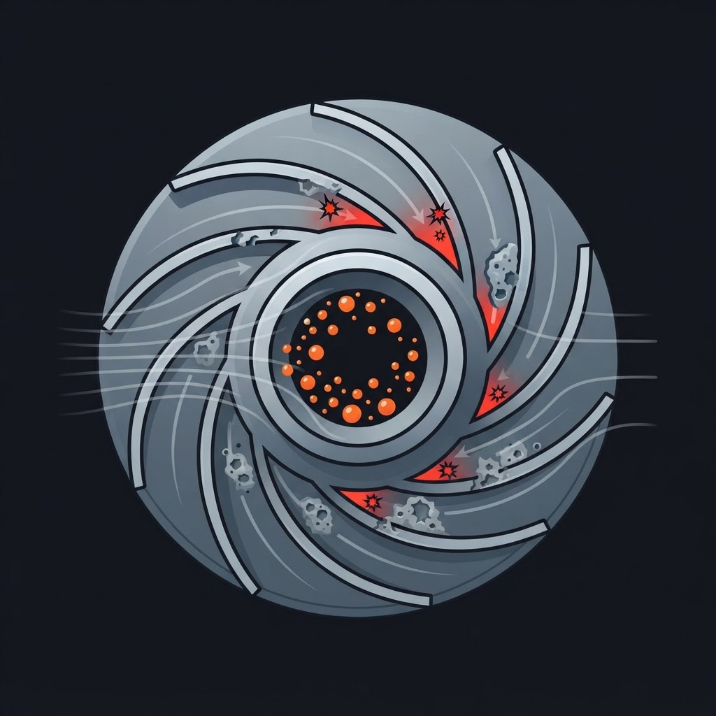
Cavitation occurs when the local pressure in the pump drops below the vapour pressure of the liquid. Vapour bubbles form in the low-pressure zone at the impeller eye. These bubbles then collapse violently as they move into the high-pressure zone — the collapse creates intense local pressure waves (microjet impingement) that erode the impeller and casing.
Symptoms of Cavitation
- Crackling or rattling noise — often described as pumping gravel or marbles
- Erratic flow and pressure fluctuations
- Vibration
- Rapid impeller and casing erosion — pitting on the impeller vanes, particularly on the low-pressure face
Net Positive Suction Head (NPSH)
NPSH is the key concept behind cavitation prevention.
NPSHr (Required)
The minimum suction head the pump needs at its inlet to operate without cavitating. Determined by the pump manufacturer — found on the pump curve or datasheet.
NPSHa (Available)
The actual suction head available at the pump inlet. Determined by the system — suction source pressure, friction losses, fluid vapour pressure, and elevation.
The Rule
NPSHa must always be greater than NPSHr. A safety margin of at least 0.5–1.0 m above NPSHr is recommended.
Factors that reduce NPSHa (and cause cavitation):
- Increase in fluid temperature (raises vapour pressure)
- Suction lift too high (pump located too far above the fluid source)
- Excessive suction pipe friction losses (undersized pipe, too many fittings, clogged strainer)
- Operating the pump above its rated flow
- High altitude (lower atmospheric pressure)
EXAM TIP
A clogged suction strainer is one of the most common causes of cavitation in service — it increases suction losses and reduces NPSHa. Checking the suction strainer is an early troubleshooting step.
Recirculation
A related phenomenon — at very low flow rates, internal recirculation occurs in the impeller, causing similar noise and damage to cavitation. The remedy is to increase flow toward BEP, not to restrict flow further.
Positive Displacement Pumps
Positive displacement pumps trap a fixed volume of fluid per cycle and force it through the discharge. Unlike centrifugal pumps, they produce the same flow at any pressure (up to the limits of the system or a relief valve). They are self-priming in most configurations.
CRITICAL SAFETY POINT
Positive displacement pumps must never be run against a closed discharge valve — with no outlet, pressure builds until something fails (pump casing, piping, or seal). A pressure relief valve is always required in the discharge circuit.
Gear Pump

Two meshing gears rotate inside a close-fitting housing. Fluid is trapped between the gear teeth and the housing on the inlet side and carried around to the discharge side as the teeth unmesh.
Types:
External gear pump
Two externally meshing spur gears. Simple, robust, common for hydraulic and lubrication systems.
Internal gear pump
One external gear meshes inside a larger internal ring gear. Smoother flow, more compact, handles higher viscosity fluids.
Applications
Hydraulic systems, lube oil systems, gear oil transfer. Handles viscous fluids well — viscosity actually improves the seal between gear teeth and housing.
EXAM TIP
Gear pumps are not suitable for fluids containing solids or abrasives — particles damage the close-fitting gear teeth and housing surfaces rapidly.
Vane Pump

A slotted rotor with sliding vanes rotates inside an oval or eccentric housing. Centrifugal force and spring pressure hold the vane tips against the housing. The expanding volume on the inlet side draws fluid in; the decreasing volume on the outlet side forces fluid out.
Applications
Hydraulic systems, fuel transfer, thin fluid applications. Lower pressure capability than gear pumps. Sensitive to contamination — vanes wear if the fluid is not clean.
Piston Pump
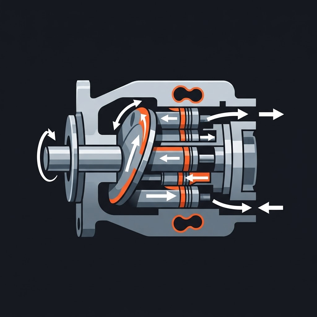
A reciprocating piston draws fluid through an inlet check valve on the suction stroke and forces it through a discharge check valve on the discharge stroke.
Types:
Axial piston pump
Pistons arranged parallel to the drive shaft in a circular pattern. Swashplate angle controls stroke length and displacement. Common in high-pressure hydraulic systems.
Radial piston pump
Pistons arranged radially around the shaft. Very high pressure capability.
Applications
High-pressure hydraulics, water jetting, chemical injection. Highest pressure capability of any pump type.
EXAM TIP
Piston pumps produce pulsating flow — each piston delivery creates a pressure pulse. Multiple pistons (typically 7 or 9 in axial designs) reduce pulsation. Accumulators dampen pulsation in sensitive systems.
Diaphragm Pump
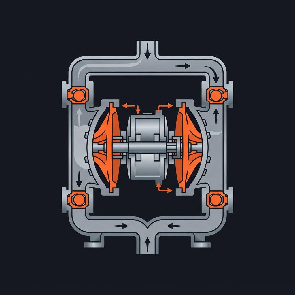
A flexible diaphragm reciprocates to create pumping action — no rotating parts contact the fluid. The diaphragm is driven mechanically or pneumatically.
Advantages:
- Completely seals the fluid from the drive mechanism — no shaft seal required
- Handles abrasive, corrosive, and hazardous fluids safely
- Self-priming, can run dry briefly without damage
- Air-operated diaphragm pumps (AODD) are intrinsically safe — no electrical components in the fluid path
Applications
Chemical transfer, abrasive slurries, hazardous fluids, paint and coatings.
EXAM TIP
A diaphragm pump that chatters or delivers erratic flow typically has a failed check valve — the check valve allows backflow instead of directing fluid through the pump in one direction.
Screw Pump
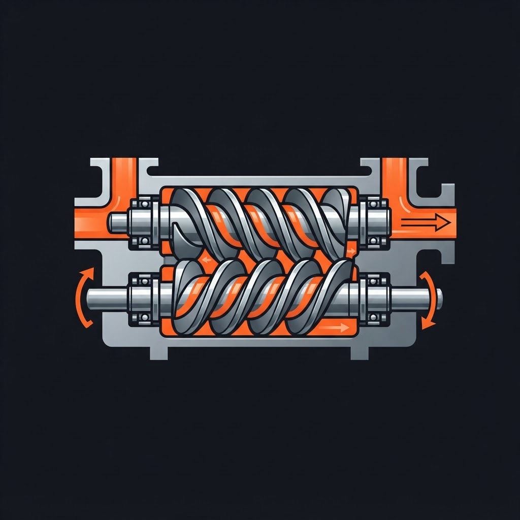
Two or three intermeshing screws rotate to move fluid axially from inlet to discharge. Extremely smooth flow, very low pulsation.
Applications
High-viscosity fluids — heavy fuel oil, crude oil, gear oil, chocolate (food industry). The screw geometry handles viscous fluids better than any other pump type.
Mechanical Seals
Mechanical seals prevent fluid from leaking along the pump shaft. They are one of the highest-frequency maintenance items on centrifugal pumps and a major exam topic.
How a Mechanical Seal Works
A mechanical seal consists of two lapped (precision flat) faces — one rotating with the shaft, one stationary in the gland plate. The faces are held together by spring force and fluid pressure. A very thin film of fluid between the faces provides lubrication and cooling — without this film, the faces run dry and fail rapidly.
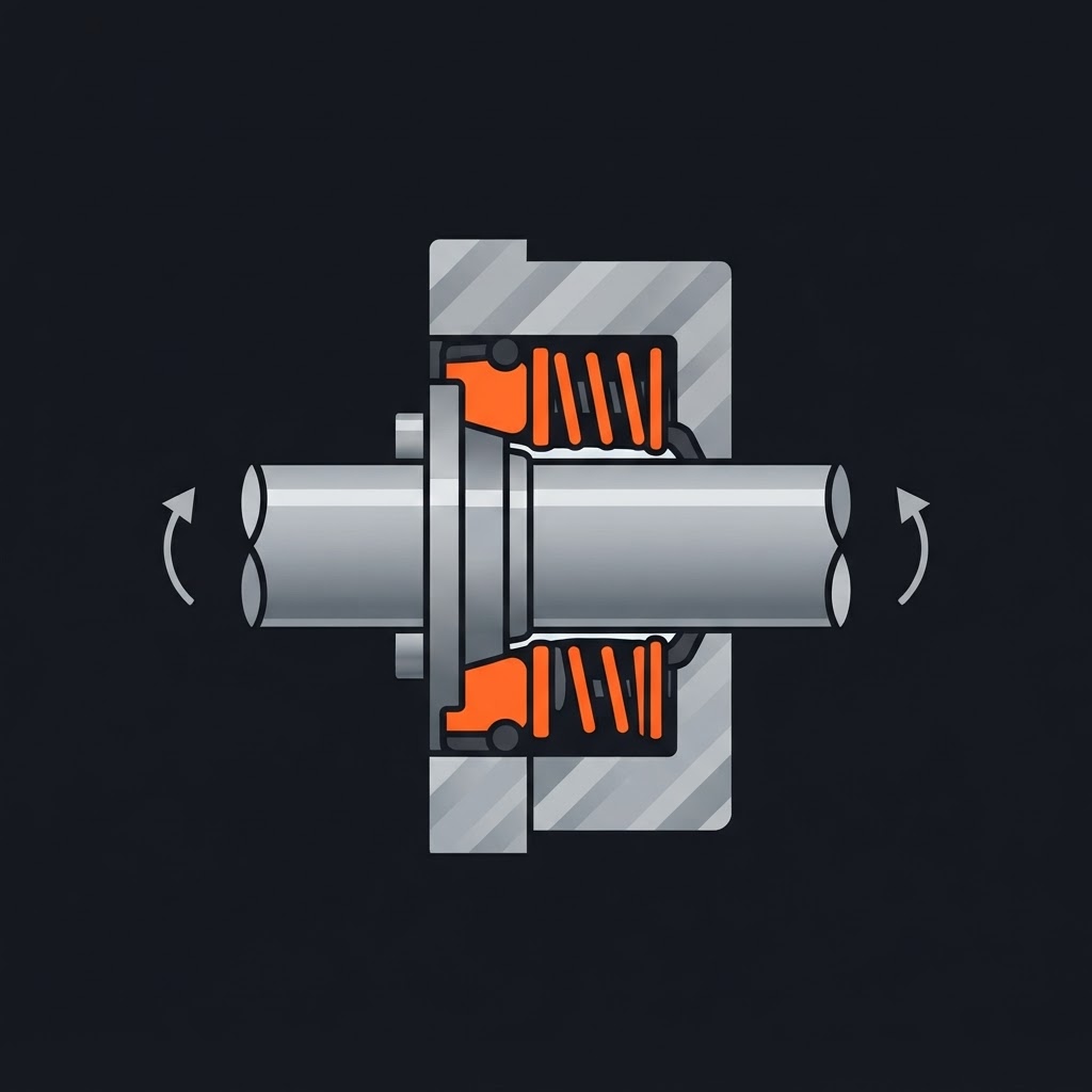
Primary Components:
Types of Mechanical Seals
Single Mechanical Seal
One set of faces. Most common. Requires the pumped fluid to be compatible with atmospheric leakage — a small amount of leakage past the faces is normal and necessary for lubrication.
Double Mechanical Seal
Two sets of faces with a barrier fluid between them. Used for hazardous, toxic, or flammable fluids where any leakage to atmosphere is unacceptable. The barrier fluid is maintained at pressure above the process fluid.
Balanced vs. Unbalanced
Unbalanced
Full fluid pressure acts on the seal faces. Limited to lower pressure applications.
Balanced
Hydraulic pressure is reduced at the seal face by undercutting the seal ring. Used at higher pressures — reduces face load and heat generation.
Mechanical Seal Installation
Mechanical seal installation is one of the most failure-prone maintenance tasks — most seal failures occur at start-up due to installation errors.
Critical Installation Points:
- 1Cleanliness: Any contamination on the seal faces causes immediate failure. Handle faces only with clean gloves, never touch the lapped faces with bare hands.
- 2Do not scratch the seal faces: Lapped faces are precision ground to optical flatness. A single scratch creates a leak path.
- 3Compression setting: The seal must be set to the correct compressed length. Too little = insufficient face load = leakage. Too much = excessive wear and heat generation.
- 4Secondary seal condition: O-rings must be compatible with the fluid and lubricated with a compatible lubricant before installation.
- 5Never run dry: A mechanical seal must have fluid at the faces before startup. Running dry for even a few seconds can destroy the faces.
EXAM TIP
Most mechanical seal failures are installation-related, not seal design failures. A new seal that fails immediately or within the first few hours of operation was almost certainly installed incorrectly or run dry during startup.
Mechanical Seal Failure Analysis
| Symptom | Likely Cause |
|---|---|
| Immediate leakage after installation | Contaminated or scratched faces, incorrect compression |
| Leakage increasing gradually | Normal wear — seal approaching end of service life |
| Sudden leakage after period of good operation | Dry running, process upset, thermal shock |
| Seal faces cracked | Thermal shock (cold fluid introduced to hot seal) |
| O-ring swollen or degraded | Chemical incompatibility |
| Heavy face wear, heat discolouration | Insufficient lubrication, dry running, excessive face load |
| Fretting on shaft | Secondary seal not sealing — shaft rotating inside the secondary seal |
Pump Troubleshooting
No Flow or Low Flow
- Pump not primed — centrifugal pump has air in the casing
- Wrong rotation — three-phase motor wired incorrectly, rotation reversed
- Suction strainer clogged
- Impeller worn or damaged
- Impeller clearance too large (wear ring worn)
- Discharge valve closed or partially closed
- Speed too low
No Pressure or Low Pressure
- Air leak on suction side
- Worn impeller or wear rings
- Operating far above BEP (excessive flow, low head)
- Impeller running in wrong direction
- Bypass valve open
Excessive Power Consumption
- Specific gravity of fluid higher than design
- Speed too high
- Mechanical friction — tight seal, bearing failure
- Operating far below BEP (centrifugal pumps consume more power at low flow in some designs)
Vibration
- Cavitation
- Misalignment
- Bearing failure
- Impeller damage or imbalance
- Resonance with piping or foundation
- Operating far from BEP (recirculation)
Overheating
- Running at shutoff head (no flow)
- Insufficient cooling flush on mechanical seal
- Bearing lubrication failure
- Fluid temperature too high
EXAM TIP
Reversed rotation is a common commissioning error on three-phase motors — swapping any two of the three phase conductors at the motor terminal corrects it. A centrifugal pump running backwards will still move some fluid but at significantly reduced head and flow.
Wear Rings
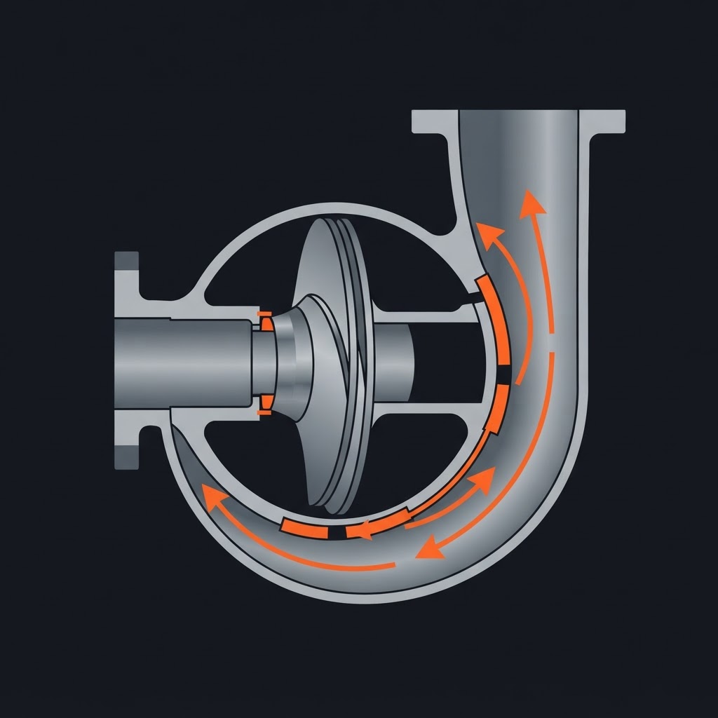
Wear rings (also called clearance rings or wearing rings) are replaceable rings fitted between the impeller and the casing to control internal recirculation. As the pump operates, the small clearance between the impeller and casing allows high-pressure fluid to leak back to the suction — wear rings minimize this leakage.
As wear rings erode, the clearance increases, internal recirculation increases, efficiency drops, and flow decreases. Wear rings are a sacrificial component — designed to be replaced rather than replacing the impeller or casing.
EXAM TIP
A centrifugal pump that has gradually lost flow and efficiency over time, with no other obvious faults, likely has worn wear rings. Clearance is measured with a feeler gauge and compared to manufacturer specifications.
Sample Exam-Style Questions
Work through these exam-style scenarios. Tap each to reveal the approach.
A centrifugal pump makes a rattling noise like marbles and shows erratic pressure readings. What is the likely cause and what are three possible contributing factors?
A positive displacement pump is started with the discharge valve closed. What will happen and why?
A centrifugal pump is installed with a concentric reducer on the suction side. What problem does this cause and what is the correct installation?
A new mechanical seal fails within two hours of startup. List three possible causes related to installation rather than seal design.
Using the affinity laws, if a pump running at 1,750 RPM produces 500 L/min at 40m of head, what flow and head would result from increasing the speed to 2,100 RPM?
A centrifugal pump that was performing well has gradually lost flow and head over several months. What component is most likely worn and how is it measured?
Frequently Asked Questions
Ready to Test Your Pump Knowledge?
Pump questions on the Red Seal exam reward millwrights who understand what's happening inside the pump, not just what the controls say. Combine this guide with practice questions to connect theory to the job.
Related guides:
Last updated: September 2026 · MW Red Seal Millwright Prep is built by a millwright, for millwrights. Content is aligned with the National Occupational Analysis (NOA) for Industrial Mechanic (Millwright) — the same document that structures the Red Seal exam.