Millwright Tools &
Precision Measurement
Precision measuring tools, hand tools, and measurement techniques explained for the Red Seal Millwright exam — micrometers, dial indicators, levels, feeler gauges, and more.
Measurement Is the Millwright's Core Skill
Any trade can turn a wrench. What separates a millwright is the ability to measure precisely, interpret what the measurement means, and make decisions based on it. Precision measurement runs through every NOA block — bearing clearances, shaft alignment, coupling installation, print tolerances, and surface finish all depend on accurate measurement with the right tool.
The Red Seal exam tests tool knowledge at two levels: identifying the correct tool for the application, and understanding how to use it correctly and interpret the reading. This guide covers both.
Measurement Units and Conversions
Canadian industry uses both metric and imperial measurement — millwrights must be fluent in both and able to convert between them.
Key conversions:
EXAM TIP
"One thou" (0.001 inch) is the common shop term for one thousandth of an inch. Precision measurement in imperial is typically expressed in thousandths or ten-thousandths of an inch. Metric precision is expressed in hundredths or thousandths of a millimetre.
Tape Measure
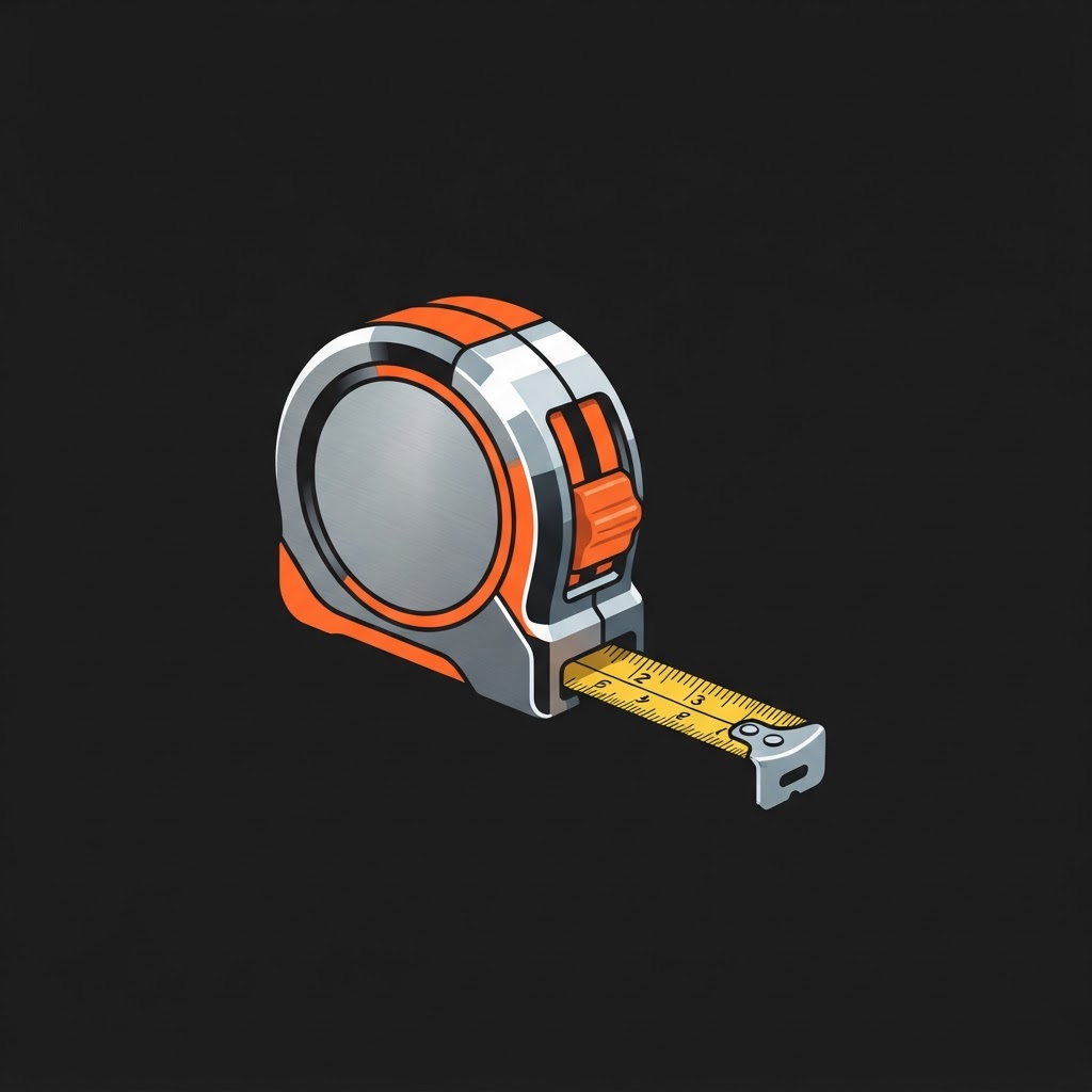
The most-used measuring tool in the trade. Every millwright carries one. Used for all general linear measurement — equipment dimensions, pipe runs, structural layout, and any measurement beyond the range of a steel rule.
Reading a tape measure:
Accuracy: ±1mm or ±1/16" in practice for general work. Not suitable for precision measurement — use for layout, rough measurement, and anything where a caliper or micrometer would be impractical.
EXAM TIP
The floating hook is intentional — not a defect. It compensates for the hook's own thickness so inside and outside measurements are both accurate from the zero mark.
Steel Rule (Scale)
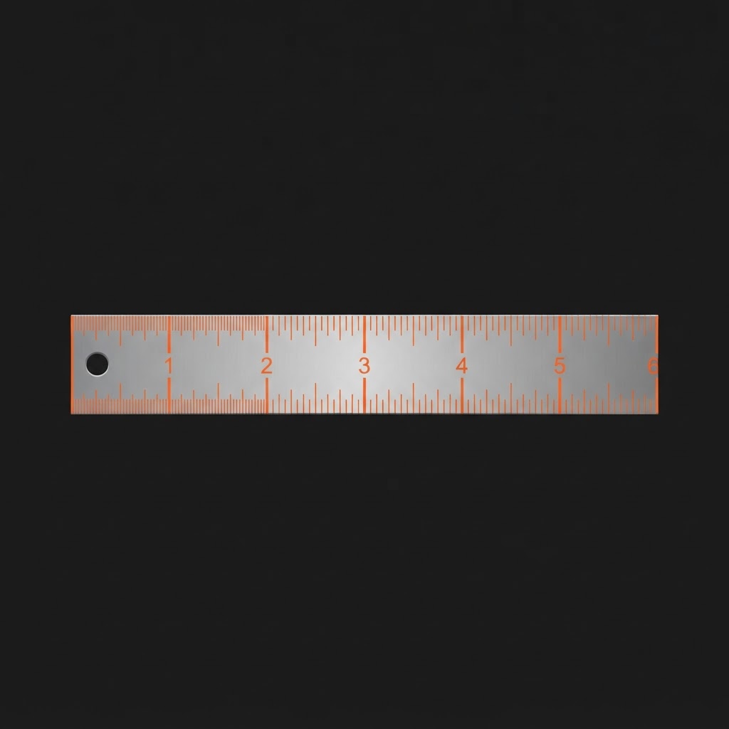
A rigid graduated rule used for layout and short-length measurement where a tape measure is impractical. Graduated in fractions of an inch (typically 1/64") and millimetres (typically 0.5mm).
Reading a steel rule accurately:
Accuracy: ±0.5mm or ±1/64" at best. Use for layout and rough measurement — not for precision work.
Vernier Caliper
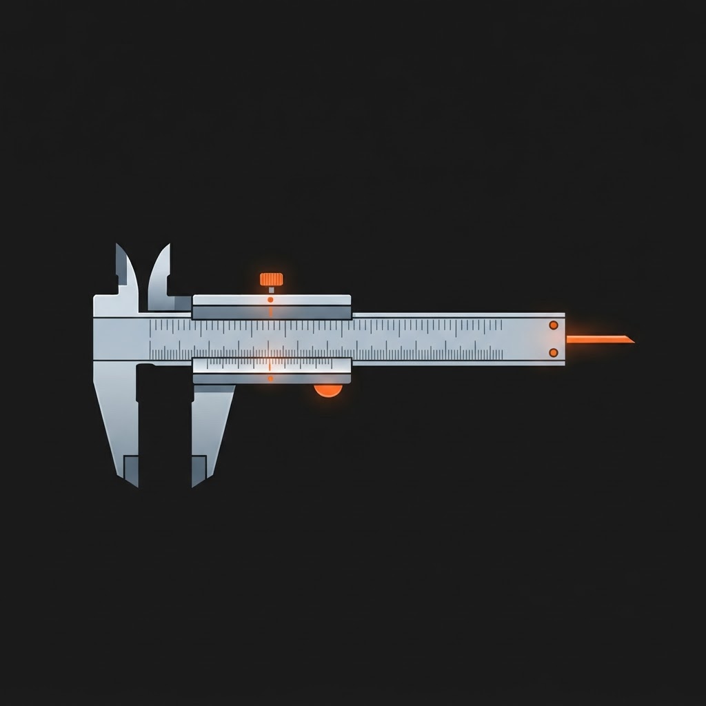
Measures outside diameter, inside diameter, depth, and step dimensions. Available in metric and imperial, digital and vernier scale versions.
Parts of a caliper:
Main scale
Fixed jaw with graduated scale
Vernier scale
Sliding jaw with secondary scale for precise reading (or digital display)
Outside jaws
Measure external dimensions
Inside jaws
Measure internal dimensions (smaller upper jaws)
Depth rod
Extends from the end of the main scale to measure depth
Lock screw
Locks the sliding jaw in position for reading
Reading a vernier caliper (analog):
Accuracy: 0.02mm (metric) or 0.001" (imperial) for a standard vernier caliper. Digital calipers typically resolve to 0.01mm.
EXAM TIP
Calipers are versatile but not the most precise tool — for measurements requiring better than 0.02mm accuracy, use a micrometer. Also check jaw condition before use — worn or damaged jaws introduce error.
Know your tools — now test it.
Practice Red Seal–style questions on measurement, tools, and technique.
Outside Micrometer
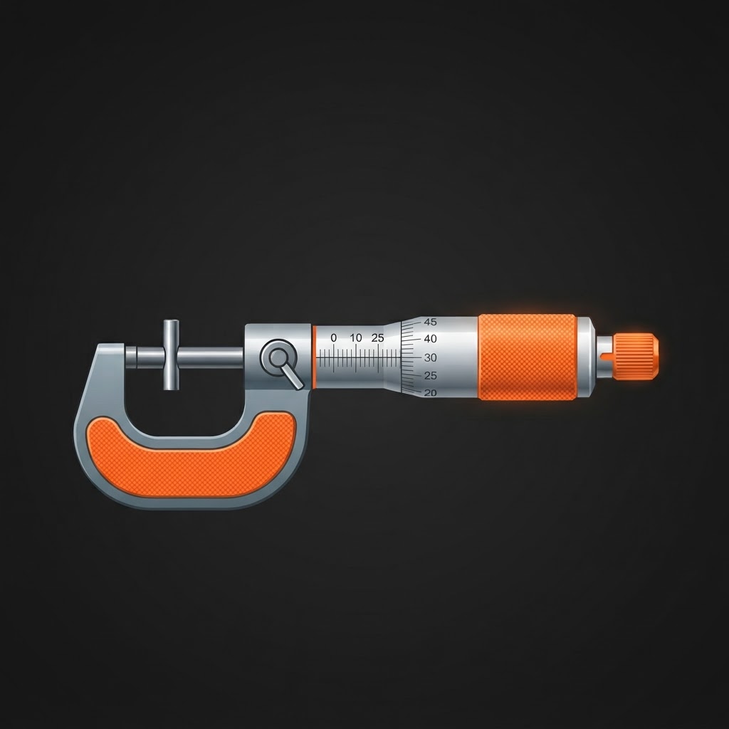
The most common precision measuring tool in the millwright trade. Measures external dimensions to 0.001" (imperial) or 0.01mm (metric), with a vernier scale adding another decimal place on some models.
Parts of a micrometer:
Frame
C-shaped body
Anvil
Fixed measuring face
Spindle
Rotating measuring face
Sleeve (barrel)
Fixed scale, graduated in 0.025" or 0.5mm increments
Thimble
Rotating scale, graduated in 0.001" or 0.01mm increments
Ratchet stop
Applies consistent measuring force to prevent over-tightening
Lock nut
Locks the spindle for reading or transfer
Reading an imperial micrometer:
Example:
Sleeve shows 3 major divisions (0.300") + 1 minor division (0.025") + thimble reads 13 (0.013") = 0.338"
Reading a metric micrometer:
Proper micrometer technique:
EXAM TIP
The ratchet stop ensures consistent measuring force. Without it, readings vary depending on how hard the spindle is tightened against the work. Always use it.
Inside Micrometer
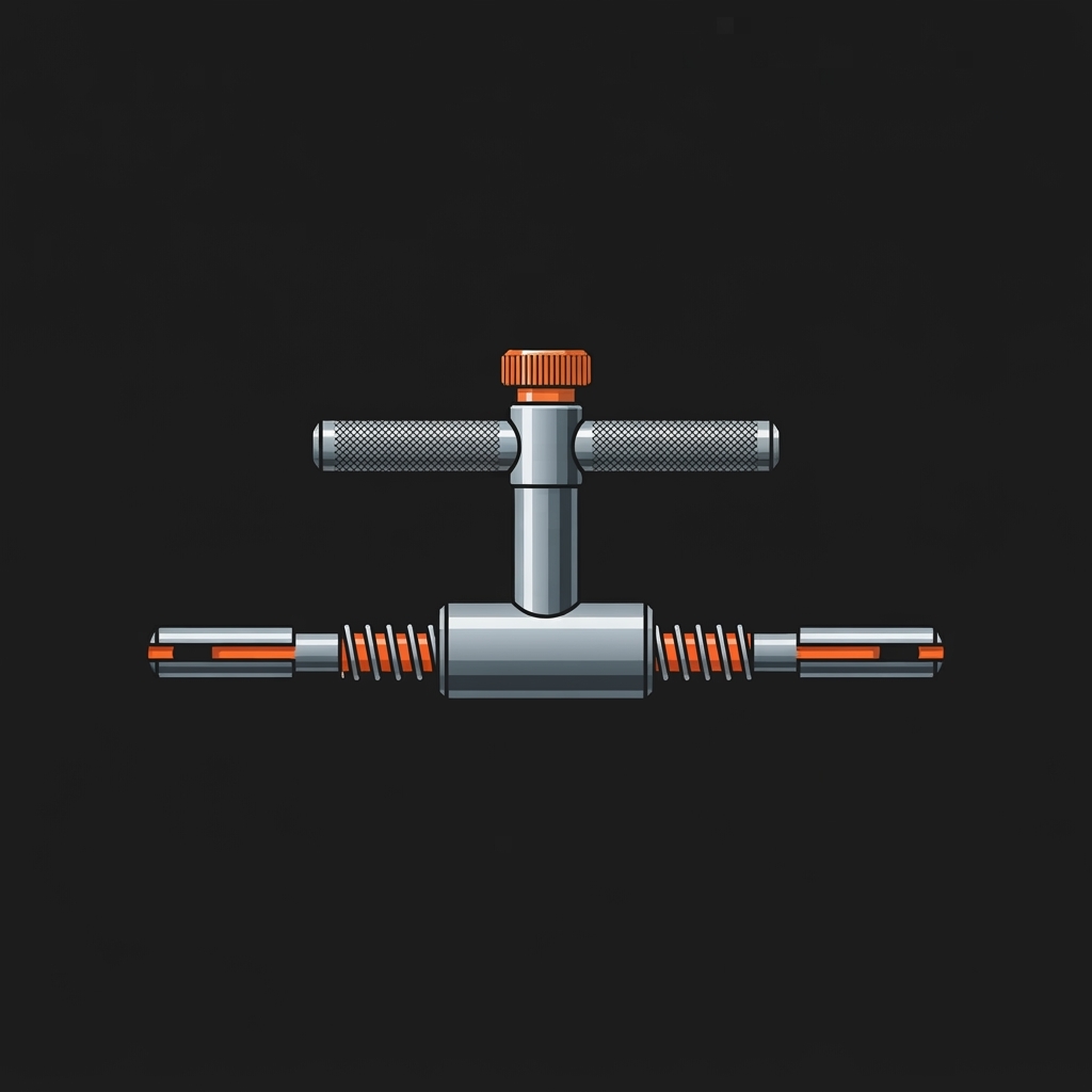
Measures internal dimensions — bores, slots, and internal grooves. Two common types:
Telescoping gauge (snap gauge)
Spring-loaded plungers expand inside a bore. Lock the gauge with the T-handle, withdraw it, and measure across the plungers with an outside micrometer. Requires skill to get a consistent reading — rock the gauge slightly to find the true diameter.
Inside micrometer set
Direct-reading micrometer with extension rods for larger bores. More accurate than the telescoping gauge method for larger diameters.
Small hole gauges (ball gauges)
For small bores where telescoping gauges won't fit. Same technique — expand inside the bore, lock, withdraw, and measure with an outside micrometer.
EXAM TIP
Telescoping gauges require technique to read accurately. The gauge must be rocked in the bore to ensure the plungers are spanning the true diameter — a tilted gauge reads smaller than the actual bore.
Depth Micrometer
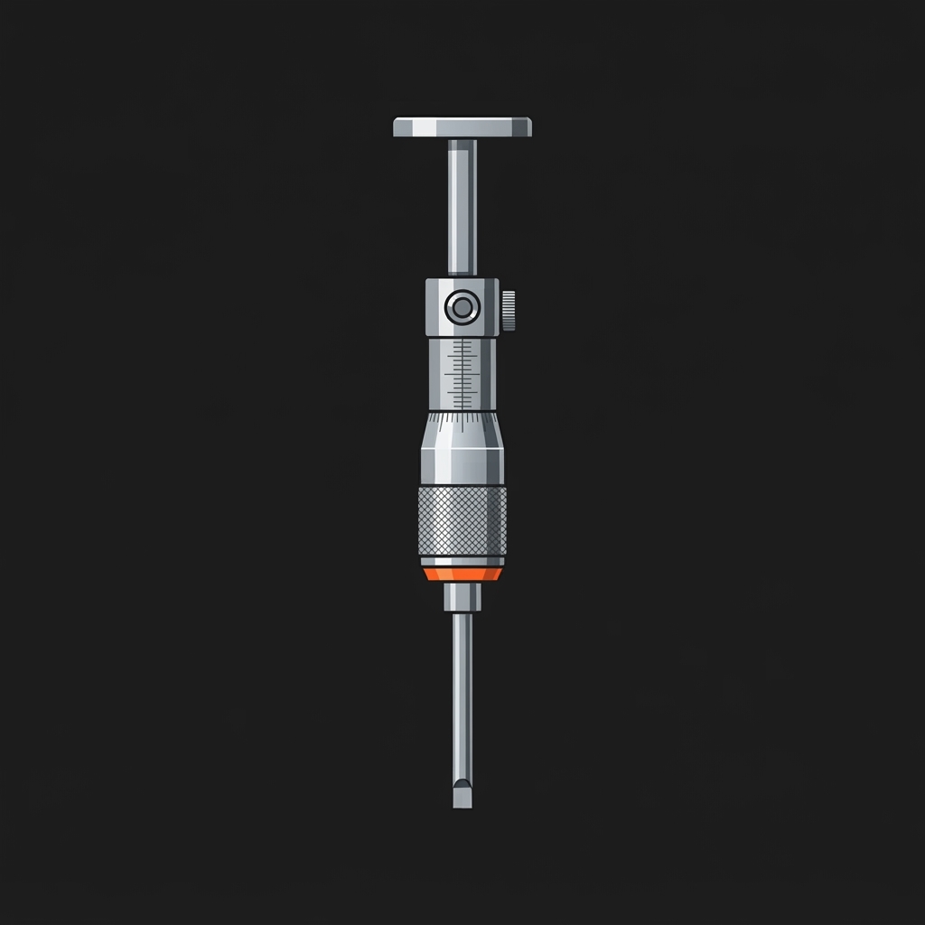
Measures the depth of slots, counterbores, steps, and recesses. The base (reference surface) sits on the workpiece surface while the spindle extends into the feature being measured.
Reading:
Same principle as an outside micrometer — sleeve and thimble readings are added. Note that the depth micrometer reads in the opposite direction to an outside micrometer (the reading increases as the spindle extends further).
Dial Indicator
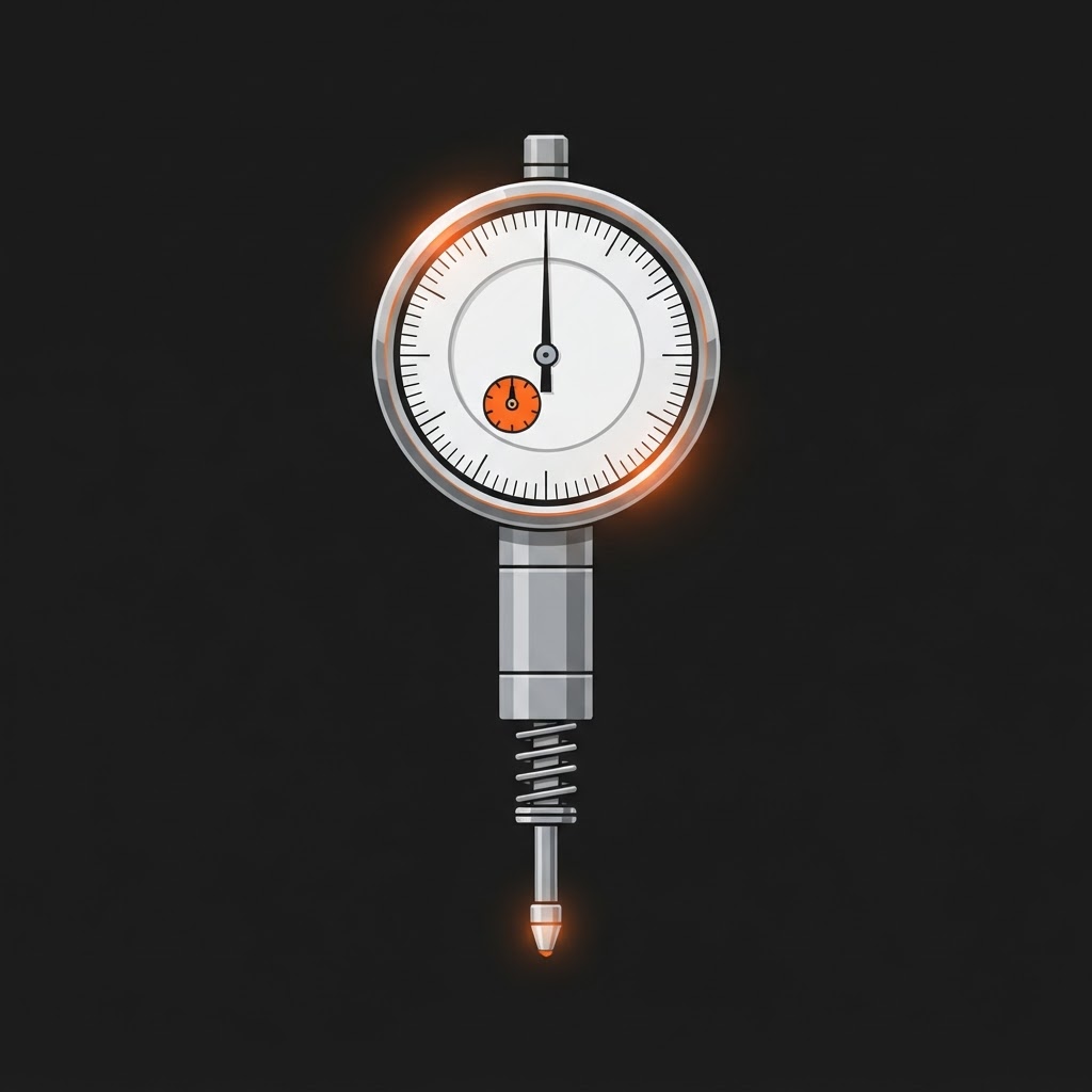
Measures small linear displacements — used for runout, alignment, concentricity, flatness, and machine setup. One of the most frequently used precision tools in millwright work.
Parts:
Contact point (stylus)
Touches the workpiece
Rack and pinion or gear train
Converts linear motion to rotary
Dial face
Graduated in 0.001" (imperial) or 0.01mm (metric) per division
Bezel
Outer ring, rotatable to zero the indicator at any position
Stem
Clamped in a magnetic base or indicator holder
Dial indicator setup:
Reading: One full revolution of the needle = one inch or one millimetre, depending on the indicator. Count full revolutions plus the partial revolution reading.
Applications:
Runout
Indicator tip contacts rotating shaft or surface; total indicator reading (TIR) is the difference between maximum and minimum readings over one full rotation
Shaft alignment
Indicator mounted on one shaft, reading taken from the other (reverse dial method)
Flatness and level
Indicator swept across a surface to check for high and low spots
End float / axial play
Indicator tip contacts shaft end, shaft moved axially
EXAM TIP
TIR (Total Indicator Reading) is the full range from lowest to highest reading. If the indicator reads +0.003" at one point and -0.005" at another, TIR = 0.008". This is the measurement of total runout or misalignment, not the average.
Dial Test Indicator (DTI)

Similar to a dial indicator but the contact point moves in an arc rather than linearly. The lever-type stylus allows measurement in confined spaces where a standard dial indicator won't fit.
Key difference from dial indicator:
DTI is less accurate over large ranges — it's most accurate when the stylus is perpendicular to the work surface (at 90°). Angular deflection of the stylus introduces cosine error. Best used for small displacement measurements and fine setup work.
Feeler Gauge
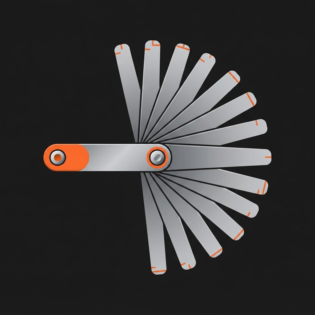
A set of hardened steel blades of precise thickness, used to measure small gaps — bearing clearances, valve clearances, gear backlash, and coupling gaps.
Using a feeler gauge:
EXAM TIP
Feeler gauges are go/no-go tools in practice — a blade that won't enter means the gap is smaller than the blade; a blade with no resistance means the gap is larger. The blade with a "light pull" is the correct thickness.
Straight Edge
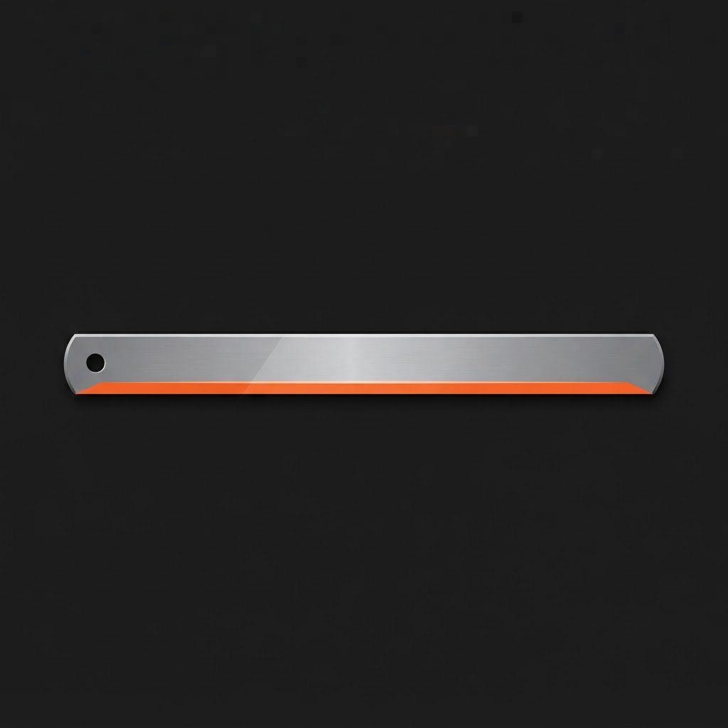
A precision ground bar used to check flatness, alignment, and surface contact. Placed on a surface — any deviation from flat is visible as a gap between the straight edge and the surface.
Using with feeler gauges
Place the straight edge across the surface, use feeler gauges to measure any gap at different points.
Using with a light source
In a dark environment, light passing under the straight edge reveals high and low spots — useful for checking machine ways and bedplates.
Precision Level
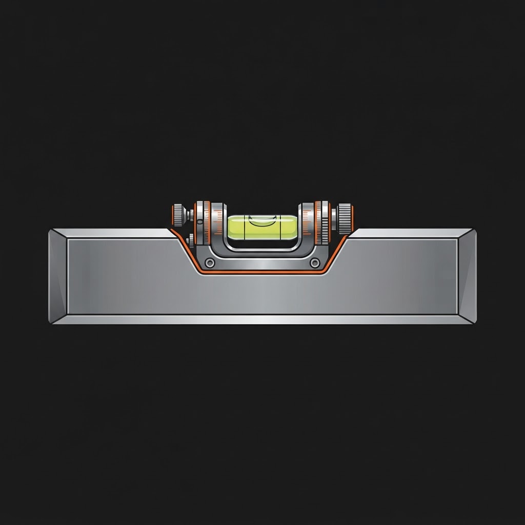
Used to establish level, check machine bases for twist, and set up equipment during installation. Two types commonly used by millwrights:
Spirit level (bubble level)
A sealed tube filled with liquid and a bubble. When the bubble centres between the graduation marks, the surface is level. Precision machinist's levels read in seconds of arc or mm per metre.
Precision machinist's level
Far more sensitive than a carpenter's level. Typically reads 0.02mm per metre per division (approximately 4 seconds of arc per division). Used for levelling machine bases, checking for twist in bedplates, and precision equipment installation.
Reading sensitivity:
A 0.02mm/m level means one division of bubble movement = 0.02mm of height difference over 1 metre of length. Over a 2-metre span, one division = 0.04mm height difference.
Checking for twist:
Place the level across the width of the machine base at multiple points along its length. Any change in level reading from front to back indicates twist.
EXAM TIP
Always check the level itself for accuracy before use — a level can be in error if it has been dropped or damaged. Rotate the level 180° on the same surface — the bubble should read the same. If it doesn't, the level vial is off.
Prussian Blue (Engineer's Blue)

A marking compound used to check the contact pattern between mating surfaces — bearings, machine ways, and seating surfaces.
Technique:
Apply a thin coat of Prussian blue to one surface, mate the surfaces together and move them slightly, then separate. The blue transfers to the high contact points on the mating surface — low areas show no transfer.
Reading the pattern
Uniform distribution of blue across the surface indicates good contact. Concentrated patches indicate high spots; clean areas indicate low spots.
Application
Checking bearing shells, fitting scraped surfaces, verifying coupling flange contact.
Torque Wrench
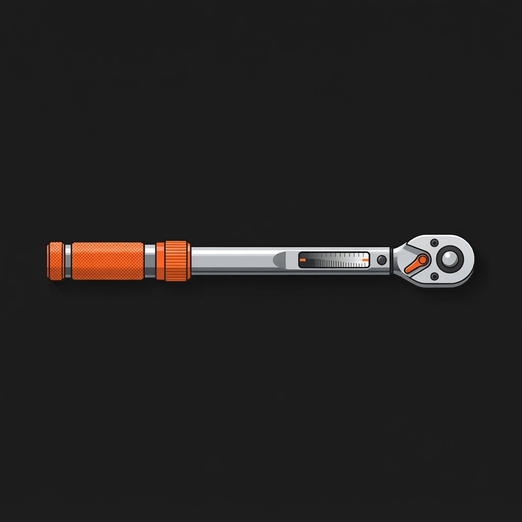
Applies a controlled amount of torque to a fastener. Critical for bolt patterns, coupling bolts, bearing locknut installation, and any fastener with a specified torque value.
Types:
Click type
Most common. Set the torque value on the handle; a click and slight give indicate the set torque has been reached. Do not use past the click — over-torquing is as damaging as under-torquing.
Beam type
A pointer on a flexible beam deflects as torque increases. Read directly from the scale. Simple and requires no calibration beyond zeroing.
Digital torque wrench
Electronic measurement with a display. Can record peak torque.
Proper technique:
EXAM TIP
Torque wrenches require periodic calibration. A torque wrench that has been dropped should be recalibrated before use. The exam may ask about proper torque sequence for a flange — always cross-pattern, working toward final torque in multiple passes.
Plastigage
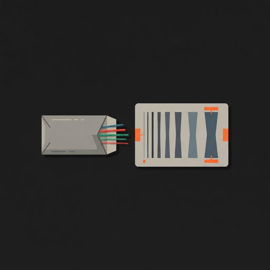
A soft plastic thread used to measure bearing clearance without precision instruments. Placed between the bearing shell and journal, the assembly is bolted to the specified torque, then disassembled. The width of the crushed Plastigage is compared to a reference card to determine clearance.
EXAM TIP
Plastigage is a one-use tool — it is crushed during measurement and cannot be reused. It measures oil clearance in plain (journal) bearings — not rolling element bearings.
V-Blocks
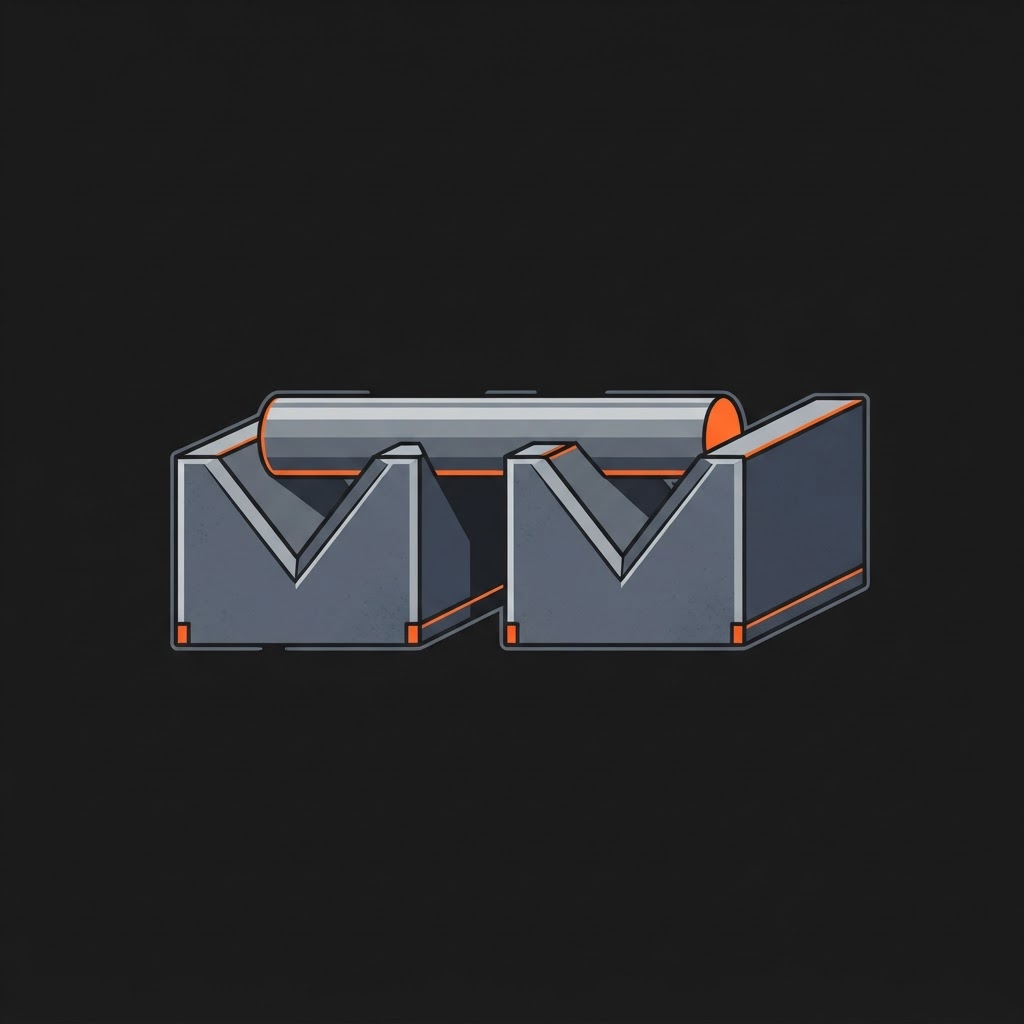
Precision ground blocks with a V-shaped groove used to support and locate cylindrical workpieces. Used in pairs to support shafts for runout measurement, straightness checking, and layout work.
The V-block self-centres the shaft — the contact points on the V locate the shaft on its centreline regardless of shaft diameter (within the V-block's capacity).
Combination Square
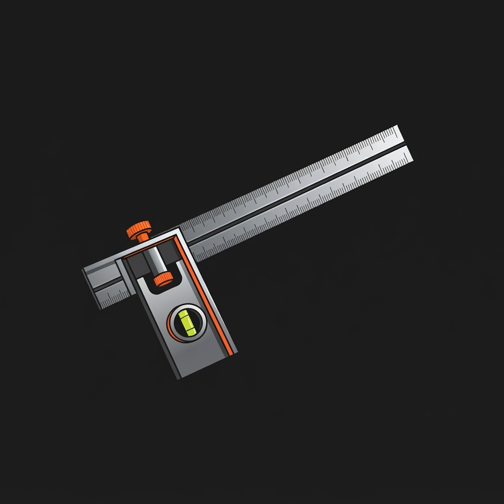
A multi-purpose layout and measurement tool consisting of a steel rule and one or more heads:
Square head
90° and 45° angles, built-in spirit level
Protractor head
Adjustable angle measurement
Centre head
Locates the centre of a round bar
Applications: Checking squareness, marking out 45° cuts, setting tool height, finding shaft centres.
Measurement Best Practices
Cleanliness
Dirt on measuring tools or workpieces introduces error. Clean both before measuring.
Temperature
Metal expands with heat. Precision measurement should be done at or near 20°C where possible. A warm shaft from machining will measure larger than it will at room temperature.
Calibration
Measuring tools should be checked for accuracy regularly and before critical measurements. A micrometer that doesn't zero correctly produces consistently wrong readings — which can be worse than an obviously broken tool.
Repetition
Take multiple measurements and compare. Consistent readings give confidence; varying readings indicate technique issues or surface irregularities worth investigating.
Right tool for the job:
Sample Exam-Style Questions
A micrometer sleeve shows two major divisions, one minor division, and the thimble reads 17. What is the measurement in inches?
A dial indicator shows a maximum reading of +0.004" and a minimum reading of -0.003" over one full shaft rotation. What is the TIR?
A telescoping gauge is used to measure a bore. The technician does not rock the gauge in the bore before locking it. What error will this introduce?
A precision level is placed across a machine base and reads two divisions to the left. The level is rotated 180° and placed in the same position — it now reads four divisions to the left. What does this indicate?
A bolt pattern on a coupling flange has six bolts. What is the correct torquing approach?
Plastigage is placed in a plain bearing assembly and torqued to specification. After disassembly, the Plastigage is 3mm wide. The reference card shows 3mm corresponds to 0.05mm clearance. What type of bearing does Plastigage measure?
Frequently Asked Questions
Key Takeaways
When studying precision measurement, focus on:
Ready to Test Your Measurement Knowledge?
Measurement questions reward millwrights who've used these tools in the shop — but knowing the theory means you won't lose marks on identification and technique questions.
Related guides:
Last updated: September 2026 · MW Red Seal Millwright Prep is built by a millwright, for millwrights. Content is aligned with the National Occupational Analysis (NOA) for Industrial Mechanic (Millwright) — the same document that structures the Red Seal exam.