Turbines Guide
for the Red Seal Millwright Exam
Steam turbines and gas turbines explained for the Red Seal Millwright exam — components, operation, maintenance, seals, bearings, and troubleshooting for millwrights.
Turbines in the Millwright Trade
Turbines are high-speed, high-energy rotating machines — among the most demanding equipment a millwright will work on. Steam turbines drive generators, compressors, and pumps in power generation, refining, pulp and paper, and chemical facilities. Gas turbines power pipeline compressors, offshore platforms, and industrial generators.
Millwrights do not design turbines or perform major overhauls independently — that work involves specialized teams and OEM support. What millwrights do is install, align, maintain, and troubleshoot turbines as part of the plant maintenance team, and the Red Seal exam tests that level of knowledge: components, operating principles, maintenance procedures, and failure analysis.
Steam Turbines — Operating Principles
A steam turbine converts the thermal energy of steam into mechanical rotation. High-pressure, high-temperature steam passes through turbine blades, expanding as it does, and the reaction or impulse force of the expanding steam spins the rotor.
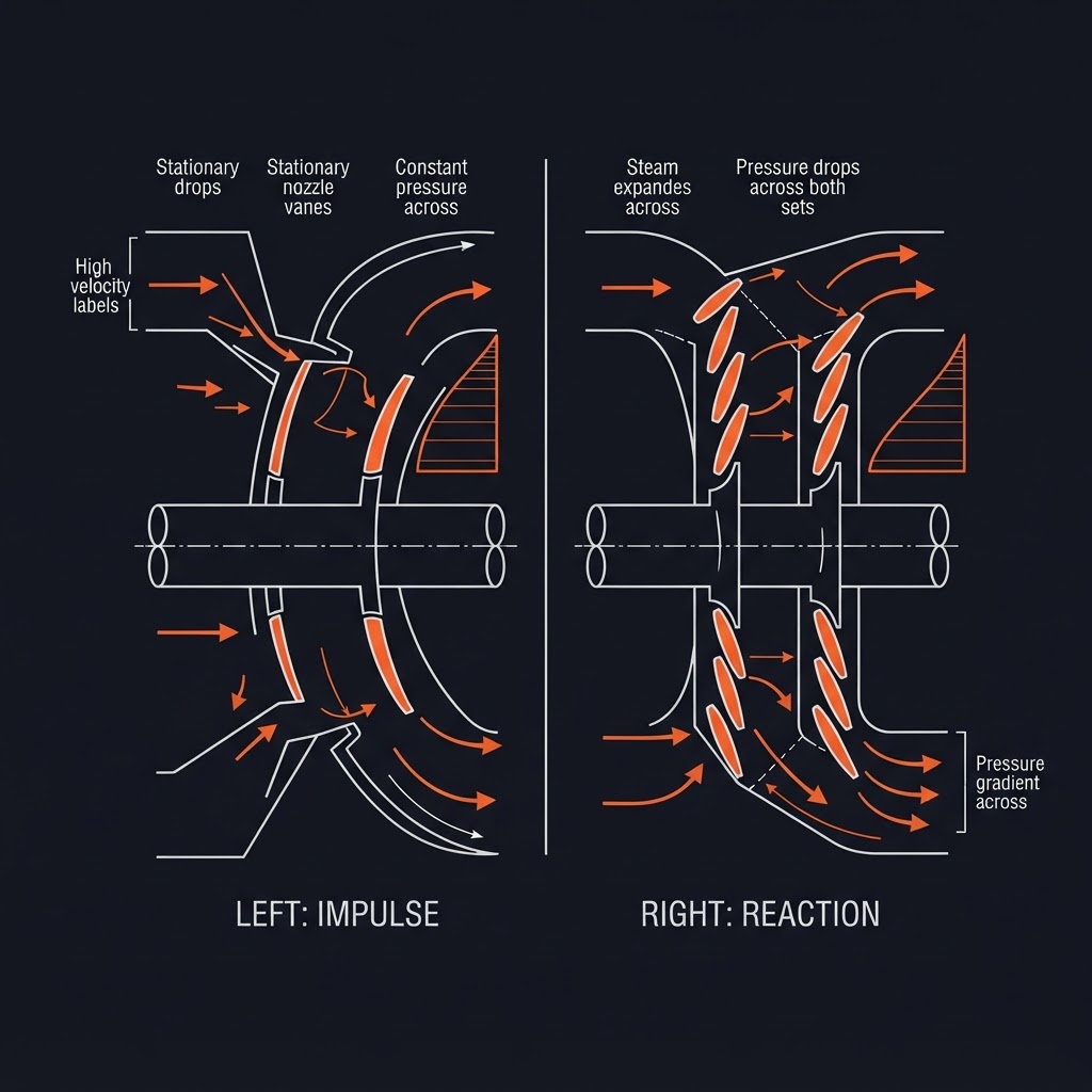
Impulse principle
High-velocity steam jets are directed at curved buckets (blades) on the rotor. The change in direction of the steam jet imparts a force on the blade. Steam pressure drops across the stationary nozzles only — pressure remains constant across the moving blades. The de Laval turbine is a pure impulse design.
Reaction principle
Steam expands across both the stationary (stator/nozzle) and rotating (rotor) blades. The rotor blades act like nozzles — steam accelerates as it passes through them, and the reaction to this acceleration drives the rotor. Pressure drops across both fixed and moving blades.
Most industrial steam turbines use a combination of impulse and reaction staging — impulse stages at the high-pressure end (where steam is densest) and reaction stages at the low-pressure end.
EXAM TIP
The key distinction between impulse and reaction is where the pressure drop occurs. Impulse — pressure drops in the fixed nozzles only. Reaction — pressure drops across both fixed and moving blades. This is a direct exam question.
Steam Turbine Classification
By steam flow direction:
Axial flow
Steam flows parallel to the rotor shaft. Most common in industrial and power generation turbines.
Radial flow
Steam flows radially outward or inward. Less common, used in some small turbines.
By exhaust condition:
Condensing
Exhaust steam is directed to a condenser operating below atmospheric pressure (vacuum), maximizing the pressure drop and extracting maximum energy. Used in power generation.
Back-pressure (non-condensing)
Exhaust steam is discharged at a usable pressure for process heating. Less efficient than condensing but the exhaust steam has value. Common in industrial cogeneration.
Extraction
Steam is extracted at one or more intermediate stages at controlled pressures for process use, with remaining steam continuing to the exhaust. Flexible for facilities with multiple steam pressure requirements.
By number of stages:
Single-stage
One set of nozzles and one rotor stage. Simple, compact, used for small drives (pumps, fans, small compressors).
Multi-stage
Multiple stages of nozzles and blades in series. Each stage extracts energy from the steam. Required for large power outputs and high efficiency.
Major Components of a Steam Turbine
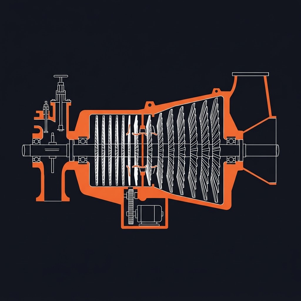
Rotor
The rotating assembly of the shaft and attached blades (buckets). Operates at very high speed — industrial turbines typically run between 3,000 and 20,000 RPM. Precision balanced to extremely tight tolerances.
Stator (casing)
The stationary outer housing. Contains the fixed nozzle blades (guide vanes) and forms the steam path. Designed to withstand high temperature and pressure differentials.
Blades (buckets)
Airfoil-shaped components that interact with steam. Moving blades attach to the rotor; stationary blades (nozzles or guide vanes) are fixed to the stator. High-temperature alloys (stainless steel or nickel-based superalloys) subject to centrifugal stress, thermal stress, and erosion.
Diaphragm
The stationary disc that holds the fixed nozzle blades between stages. Separates the steam pressure between stages.
Inlet steam chest
The chamber that receives inlet steam from the supply line and distributes it to the first stage nozzles. Contains the main stop valve and governing valves.
Exhaust hood
The casing that collects exhaust steam from the last stage and directs it to the condenser or process system.
Turning gear
A slow-speed drive (typically electric motor driven) that rotates the turbine rotor slowly during startup and shutdown. Prevents the rotor from bowing (sagging) due to thermal gradients when the turbine is stationary but still hot.
EXAM TIP
Turning gear is a critical component — a turbine rotor that is allowed to sit stationary while still hot will develop a thermal bow. If the turbine is then started with a bowed rotor, the resulting vibration can destroy blading, seals, and bearings in seconds. Never bypass the turning gear requirement.
Steam Turbine Bearings
Turbines operate at very high speeds — rolling element bearings are generally not suitable for large steam turbines. Plain (journal) bearings are used for radial support; thrust bearings handle axial loads.
Journal bearings
The turbine shaft rotates inside a precision-bored bearing lined with babbitt (white metal). A pressurized oil film separates the shaft from the bearing surface — the shaft must never contact the babbitt.
Tilting pad journal bearings
Multiple pads tilt to maintain the optimum oil film geometry as operating conditions change. More stable than fixed-geometry bearings at high speeds.
Thrust bearings
Prevent axial movement of the rotor. Steam turbines develop significant axial thrust as steam pushes against the blades. A thrust bearing (often Kingsbury type with tilting pads) absorbs this thrust.
Lube oil system
A dedicated pressurized system supplies filtered, cooled oil to all turbine bearings — main, auxiliary, and emergency pumps with cooler, duplex filters, and reservoir.
Lube oil system components:
Main oil pump
Shaft-driven or motor-driven — primary oil supply during normal operation.
Auxiliary oil pump
Motor-driven; starts automatically on low oil pressure. Verified during commissioning and regular testing.
Emergency oil pump
DC motor or accumulator-driven; activates on total power failure to protect the bearings during coastdown.
Oil cooler
Removes heat from the oil to maintain viscosity and film strength.
Duplex filters
One active, one standby — switchable without shutdown.
Oil reservoir (tank)
Bulk oil storage with de-aeration and level monitoring.
EXAM TIP
The lube oil system has three pumps precisely because bearing failure from loss of oil is catastrophic at turbine speeds. The emergency pump activates on total power failure to protect the bearings during coastdown. The auxiliary pump must start automatically on low oil pressure — this is verified during commissioning and regular testing.
Steam Sealing Systems
Steam turbines require sealing where the shaft passes through the casing — to prevent steam from escaping outward at the high-pressure end and air from being drawn in at the low-pressure (vacuum) end.
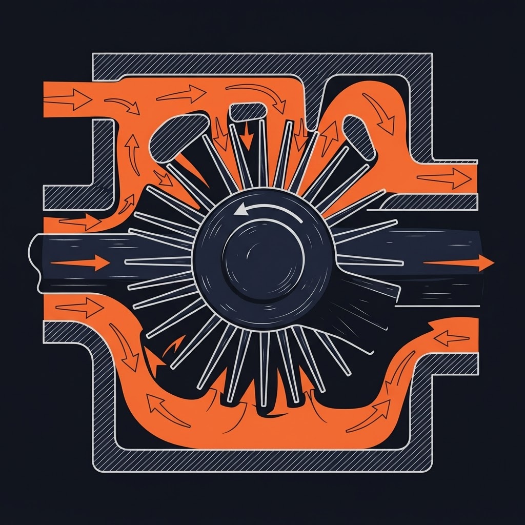
Labyrinth seals
A series of thin fins on the shaft or casing create a tortuous path that restricts steam flow without contact. Steam loses pressure at each restriction. No contact — no wear, no friction. Clearances typically 0.25–0.75mm; if the rotor contacts the fins they are wiped away and clearances increase.
Gland sealing system
For condensing turbines operating under vacuum at the exhaust end, a gland sealing system supplies low-pressure steam to the shaft seals to prevent air ingestion. A gland condenser (exhauster) removes the seal steam and any air mixture.
Carbon ring seals
Used in smaller turbines. Split carbon rings are held against the shaft by garter springs, providing a contact seal. Carbon seals wear and require periodic replacement.
Steam Turbine Governing and Control
Governor
Controls turbine speed by regulating steam admission. As speed rises above setpoint, the governor closes the governing valves; as speed drops, it opens them. Modern turbines use electronic (digital) governors; older turbines use mechanical or hydraulic governors.
Overspeed trip
A hardwired safety device that trips the turbine (closes the main stop valve) if speed exceeds a set limit (typically 110% of rated speed). Overspeed is one of the most dangerous turbine failure modes — a rotor that exceeds design speed can throw blades and destroy the casing.
Main stop valve (emergency stop valve)
A fast-acting valve that cuts off all steam to the turbine on trip. Must close rapidly and completely on any trip signal.
EXAM TIP
The overspeed trip system must be tested on a defined schedule — it is a safety-critical device. A turbine that trips on overspeed has been protected; a turbine whose overspeed trip fails to actuate can destroy itself and surrounding equipment. Testing frequency and procedure are determined by the OEM and regulatory requirements.
Steam Quality
Steam quality significantly affects turbine life and performance.
Wet steam
Steam containing moisture droplets. Droplets impacting turbine blades at high velocity cause erosion — particularly at the last stages where steam has cooled and condensed. Moisture erosion produces characteristic pitting on the leading edges of last-stage blades.
Steam purity
Dissolved solids in steam deposit on turbine blades as the steam expands and cools. Scale deposits reduce flow area, unbalance the rotor, and cause blade corrosion. Maintained through boiler water treatment and steam washing.
Superheated steam
Steam heated above its saturation temperature at a given pressure. Superheating increases energy content and eliminates moisture in the early stages of expansion. Most power generation turbines use superheated steam.
EXAM TIP
Moisture erosion on last-stage blades and solid deposits on nozzles and blades are the two most common steam quality-related turbine problems. Both are prevented by proper steam conditioning upstream of the turbine.
Steam Turbine Maintenance
Vibration monitoring
Continuous vibration monitoring is standard on industrial steam turbines. Vibration is the primary indicator of developing problems — rotor imbalance, bearing deterioration, blade damage, and rubs all manifest as changes in the vibration signature.
Oil analysis
Routine oil sampling monitors for bearing wear metals (babbitt — tin and lead), water contamination, and lubricant degradation.
Blade inspection
During planned outages, blades are inspected for erosion, corrosion, deposits, cracking, and mechanical damage. NDT (dye penetrant, magnetic particle on ferromagnetic blades) finds surface cracks.
Clearance checks
Diaphragm clearances, labyrinth seal clearances, and bearing clearances are measured and compared to allowable limits during overhaul.
Rotor runout
Rotor straightness is verified by measuring runout at multiple points along the shaft using dial indicators on V-blocks or in the bearing housings.
Balancing
If blades have been replaced or significant material removed from the rotor, dynamic balancing is performed before return to service.
Gas Turbines — Operating Principle (Brayton Cycle)
A gas turbine (also called a combustion turbine) burns fuel continuously to produce a high-temperature, high-pressure gas stream that drives a turbine. Unlike a reciprocating engine, there are no pistons — combustion is continuous and the flow is steady.
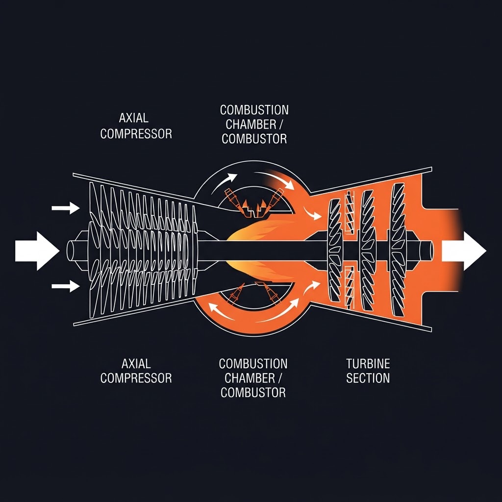
The Brayton cycle — three basic processes:
Compression
Ambient air is drawn into the compressor and compressed to high pressure. The compressor is driven by the turbine — typically consuming 50–60% of the turbine's gross output just to drive the compressor. The remaining output (net power) drives the load.
Combustion
Compressed air enters the combustion chamber (combustor) where fuel is injected and burned continuously. The combustion products (hot, high-pressure gas) exit the combustor at temperatures of 1,000–1,600°C.
Expansion
Hot combustion gases expand through the turbine stages, driving the rotor. The exhaust gas exits at near-atmospheric pressure and elevated temperature (typically 400–600°C exhaust temperature).
Thermal efficiency
Simple-cycle gas turbines have lower thermal efficiency than steam turbines (typically 30–40%) because of the high exhaust temperature — significant energy leaves with the exhaust gas. Combined cycle plants recover this exhaust heat in a heat recovery steam generator (HRSG) to generate steam for a steam turbine, achieving overall efficiencies of 55–60%.
Major Components of a Gas Turbine
Inlet air system
Filters, silencers, and ducting that clean and direct air to the compressor. Air quality is critical — particulate contamination erodes compressor blades and fouls the hot section.
Axial compressor
Multiple stages of alternating rotating (rotor) and stationary (stator) blade rows that progressively compress the air. Pressure ratios of 15:1 to 40:1 are typical in modern industrial gas turbines.
Combustion chamber (combustor)
Where fuel and compressed air mix and burn. Types: can combustors (individual cylindrical cans), annular (a single ring-shaped chamber — standard in modern turbines), and can-annular (a combination).
Transition pieces
Connect the combustor exit to the turbine inlet, directing hot gas to the first turbine stage. Highly stressed — exposed to the highest temperatures in the machine.
Turbine section
Typically two to four stages of expansion. The first stage operates at the highest temperature and is the most thermally stressed component in the entire machine.
Exhaust system
Collects and directs exhaust gas. In simple cycle, discharged to atmosphere through a stack. In combined cycle, directed to the HRSG.
Turbine blades (hot section) — surviving beyond the melting point:
- Advanced nickel superalloys
- Thermal barrier coatings (TBC) — ceramic coatings that insulate the metal from the hot gas
- Internal cooling — air bled from the compressor flows through internal passages in the blade
- Single crystal or directionally solidified grain structure — eliminates grain boundaries perpendicular to the major stress direction
EXAM TIP
Hot section components (combustor liners, transition pieces, first and second stage turbine blades and vanes) are the highest-wear, shortest-life components in a gas turbine. Inspection intervals are determined by fired hours and number of starts — starts are particularly damaging due to thermal cycling.
Gas Turbine Bearings and Lubrication
Gas turbines use tilting-pad journal bearings and thrust bearings — similar to steam turbines. The lube oil system design is also similar: main pump, auxiliary pump, emergency pump, cooler, duplex filters, and reservoir.
Key difference from steam turbines
Gas turbine exhaust temperatures are very high, and the turbine runs in a very hot environment. Lube oil must be carefully managed to prevent oil from reaching hot surfaces — oil fires are a serious hazard.
Oil mist detection
Systems are installed to detect oil mist (indicating a leak near hot surfaces) and trigger alarms or shutdowns before ignition occurs.
Gas Turbine Starting
Large gas turbines require a starting system to accelerate the rotor to self-sustaining speed before fuel is introduced and combustion begins.
Starting methods:
Electric motor (static frequency converter)
Most common in modern turbines. A variable-frequency electric motor accelerates the turbine to ignition speed, assists during light-off, then disconnects when self-sustaining.
Starting diesel engine
A diesel engine coupled through a torque converter drives the turbine during start.
Hydraulic starting
High-pressure hydraulic fluid drives a hydraulic motor coupled to the turbine shaft.
Compressed air starting
Air admitted to the turbine drives it as an air motor.
Start sequence:
EXAM TIP
The purge sequence before ignition is a safety-critical step — bypassing the purge to save time is a serious violation. Residual fuel in the turbine casing during light-off causes a combustion explosion. This is tested directly on the exam.
Gas Turbine Inlet Air Cooling
Compressor performance (and therefore gas turbine output) is highly dependent on inlet air temperature — hot air is less dense, so the compressor moves less mass per revolution, reducing power output.
Evaporative cooling
Water is sprayed into the inlet air stream. Evaporation cools the air. Limited effectiveness in high-humidity conditions.
Inlet chilling
Refrigeration system cools the inlet air below ambient temperature. More effective than evaporative cooling, particularly in hot, humid climates.
Fogging
Very fine water droplets are injected. Some evaporate in the inlet duct (evaporative cooling); some carry through to the compressor where they evaporate inside, providing intercooling.
Gas Turbine Maintenance
Inspection intervals
Governed by fired hours and equivalent operating hours (EOH), which weights starts more heavily than running hours due to the thermal cycling damage starts cause.
Borescope inspection
A flexible optical instrument inserted through inspection ports allows visual inspection of compressor blades, combustor components, and turbine blading without disassembly. Standard practice between major overhauls.
Compressor washing
Salt, dust, and other contaminants foul compressor blades, reducing efficiency and increasing corrosion risk. Offline washing (turbine shut down, cleaning solution sprayed through the inlet) and online washing (injected during operation) are both used.
Hot section inspection
Combustor liners, transition pieces, and first-stage turbine components are inspected at defined intervals. Thermal barrier coating condition, blade cooling hole blockage, and crack development are primary concerns.
Turbine blade replacement
Hot section blades have finite life. Life consumption is tracked in equivalent operating hours. Blades are replaced as a set — mixing new and used blades of different wear states unbalances the rotor.
Turbine Troubleshooting
Steam turbine:
| Symptom | Likely Cause |
|---|---|
| High vibration at 1× speed | Rotor imbalance, blade deposit, rub |
| High vibration at 2× speed | Misalignment, looseness |
| Bearing temperature rising | Low oil flow, oil contamination, bearing wear |
| Axial position shift | Thrust bearing wear, steam thrust change |
| Speed instability (hunting) | Governor fault, steam admission valve issue |
| Excessive steam consumption | Blade erosion, deposit on nozzles, seal wear |
| Oil in steam | Lube oil seal failure — bearing oil ingestion into steam path |
| High vibration on startup | Rotor bow — turning gear not used or failed |
Gas turbine:
| Symptom | Likely Cause |
|---|---|
| High exhaust temperature | Compressor fouling, combustor fault, hot section damage |
| Power output below rated | Compressor fouling, inlet filter restriction, high ambient temperature |
| High vibration | Compressor blade damage, imbalance, bearing wear |
| Combustion instability (rumble) | Fuel system fault, combustor liner damage, air-fuel ratio issue |
| Lube oil temperature high | Cooler fouling, high ambient, excessive bearing clearance |
| Failed to light off | Igniter fault, fuel system fault, purge incomplete |
| Compressor surge | Excessive fouling, damaged blading, operating outside design envelope |
Compressor surge
A dramatic flow reversal in the axial compressor caused by blade stall. Characterized by a loud bang or repeated banging, sudden vibration, and flameout. Compressor surge can damage blading rapidly — the turbine must be shut down immediately. Root causes include fouled blades reducing airflow margin, damaged blading, and operating outside the design envelope.
EXAM TIP
Compressor surge is a shutdown condition — not something to investigate while the machine is running. The characteristic sound (loud bang or repeated surging) combined with sudden vibration is the diagnostic signature. Shut down, investigate, and correct the root cause before restarting.
Turbine Safety
Steam:
- High-pressure, high-temperature steam causes severe burns on contact — all steam piping and turbine casings must be properly insulated and guarded
- Steam leaks from labyrinth seals are invisible at high pressure — never probe for steam leaks with your hand
- Isolate all steam supply lines and verify zero pressure before any turbine maintenance
Gas turbine:
- Hot section components retain extreme heat for extended periods after shutdown — allow adequate cooling time before maintenance access
- Fuel gas systems require hazardous area protocols — no ignition sources during purging or maintenance
- The exhaust duct of a recently shut down gas turbine is extremely hot — treat as a confined space with thermal hazard
Key Points for the Exam
Sample Exam-Style Questions
Work through these exam-style scenarios. Tap each to reveal the approach.
A steam turbine uses impulse staging in the first stages and reaction staging in the later stages. Explain the difference in where the pressure drop occurs in each stage type.
A steam turbine rotor is left stationary after shutdown without the turning gear running. The turbine is started the following morning and immediately shows very high vibration. What is the most likely cause?
Why does a gas turbine require a purge sequence before fuel admission during a start? What is the consequence of bypassing this step?
A gas turbine is producing less power than rated on a hot summer day compared to a cool day with no other changes. What is the cause and why?
A steam turbine is found to have an increasing axial position reading over several weeks. What component is most likely worn and what is the consequence if it is not addressed?
What is compressor surge in a gas turbine and what are the immediate actions when it is detected?
Frequently Asked Questions
Ready to Test Your Turbine Knowledge?
Turbine questions on the Red Seal exam test understanding of operating principles and consequences — not just component names. Work through the practice questions to connect theory to real machine behaviour.
Related guides:
Last updated: September 2026 · MW Red Seal Millwright Prep is built by a millwright, for millwrights. Content is aligned with the National Occupational Analysis (NOA) for Industrial Mechanic (Millwright) — the same document that structures the Red Seal exam.